Adaptive Robust Learning Control for a 6-DOF Robotic Arm with Real-Time Object Detection
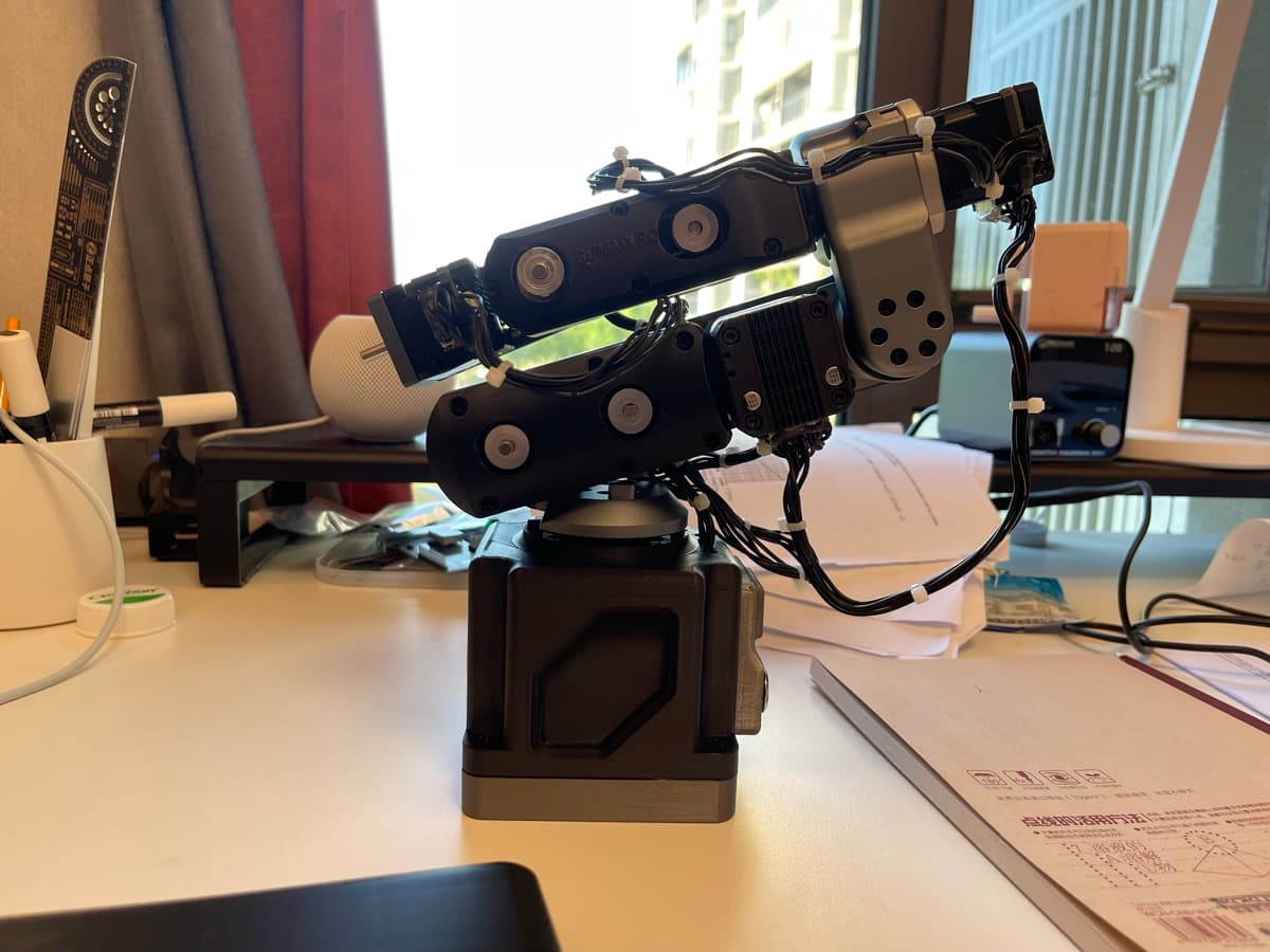
Built a low-cost 6-DOF robotic arm from the ground up, using an open-source design as the starting point and rebuilding the hardware, perception, and control stack.
Result
55.39% lower tracking RMSE than PID · 0.98 mAP@0.5 · Published in ACE
Areas
Robotics, Control Theory, Computer Vision, Mechanical Design, System Integration
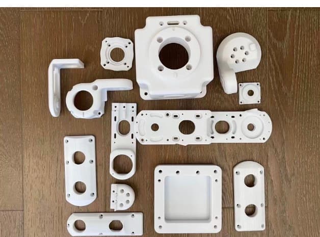
The build started from Peng Zhihui's open-source Dummy Robot arm, which depended on expensive CNC-machined components and imported harmonic reducers, pushing the estimated cost above RMB 10,000. I replaced parts of that stack with lower-cost reducers and PETG structures. The cost fell, but backlash, compliance, and manufacturing uncertainty became first-order control problems.
Instead of treating these constraints only as defects, I reframed them as a research question: could a learning-based controller recover precision from an affordable mechanical system?
System
Built across the full robotics stack
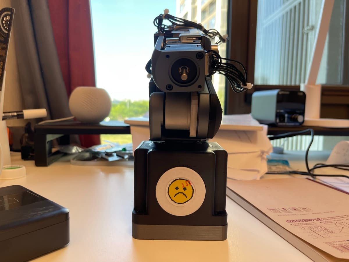
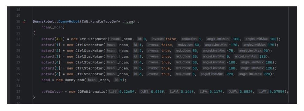
I integrated a custom six-degree-of-freedom arm using harmonic reducers, stepper motors, motor-control PCBs, CAN communication, a custom gripper, and a Gemini Pro depth camera. I designed the gripper in Autodesk Fusion 360 and produced both CNC-machined and PETG 3D-printed variants.
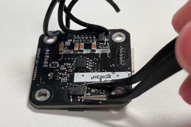
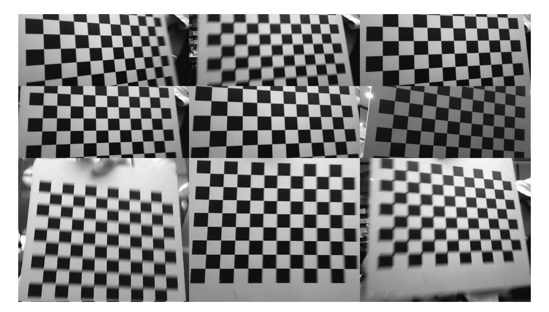
The implementation included sourcing components, assembling and soldering PCBs, installing firmware, calibrating motors and cameras, resolving mechanical tolerances, and integrating the complete ROS-based system.
Mechanical design
A gripper of my own
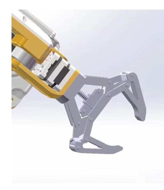
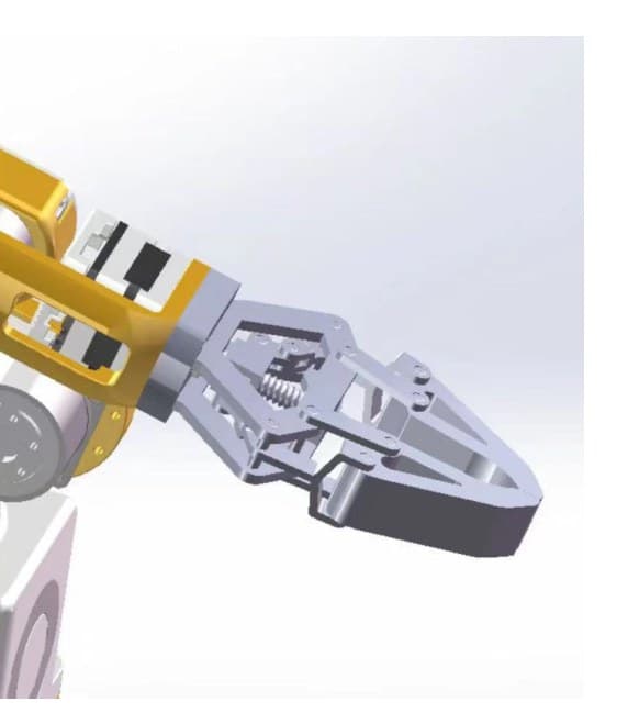
The open-source arm didn't come with an end effector built for vision-guided grasping, so I designed one myself in Autodesk Fusion 360: a worm-screw drive feeding a symmetric four-bar linkage, so a single small motor closes both jaws in sync with enough mechanical advantage to hold parts steady. The worm drive is self-locking — grip force can't back-drive the screw, so a grasped part stays held with zero holding current, even with the motor powered off.
The first revision taught me a hardware lesson: I hadn't left a long enough shaft at the end joint, and the gripper couldn't seat onto the wrist motor. After days of redesign, the final version bolts on cleanly, carries the depth camera on top so the arm sees exactly what it's about to grab, and was produced in both CNC-machined and PETG 3D-printed variants.
jaws open · worm screw + four-bar linkagejaws closed · mounted on the wrist joint
Perception
Real-time detection at the end effector
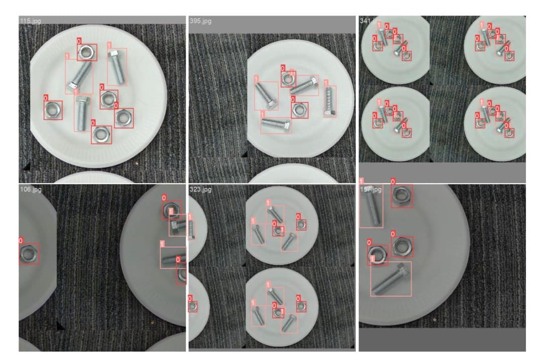
I mounted the depth camera on the end effector, prepared a custom dataset, and trained YOLOv10 to recognize and locate nuts and screws in real time. The model reached 97% classification accuracy for both classes and a mAP@0.5 of 0.98.
Combining depth and object detection allowed the perception pipeline to produce spatial targets for manipulation rather than isolated image classifications.
ADAPTIVE 6-DOF ROBOTIC ARM · BUILD LOG 02 — PERCEPTION + CONTROL
ALGORITHM BOARD
ADAPTIVE 6-DOF ROBOTIC ARM · BUILD LOG 02 — PERCEPTION + CONTROL
The stock firmware closes every joint loop with PID: multiply the error, integrate it, differentiate it, sum the three terms. That works when the plant is stiff and well modeled. My plant was neither — budget harmonic reducers with visible backlash and PETG links that flex under load.
The failure mode is telling: run the same trajectory ten times and PID makes the same mistake ten times. The error is largely repeatable, which means it carries information — and a fixed-gain controller throws that information away on every lap.
PID — fixed gains, no memory
u(t) = Kp·e(t) + Ki·∫₀ᵗ e(τ)dτ + Kd·de(t)/dt
Control · II
Learning from repetition (ILC)
Iterative Learning Control treats each repetition like a basketball player practicing free throws: keep the whole control signal from the last attempt, and correct it with the last attempt's error. Instead of retuning gains, the controller learns a compensation signal.
Substituting the update law into the system dynamics gives eₖ₊₁ = (I − CBL)·eₖ, so the tracking error contracts to zero whenever the spectral radius ρ(I − CBL) < 1 — a clean convergence guarantee.
The catch: ILC assumes the world is identical on every lap. Nudge the arm, change the payload, or let a cheap reducer's backlash shift, and the learned signal is suddenly wrong — and stays wrong until many laps re-absorb the change.
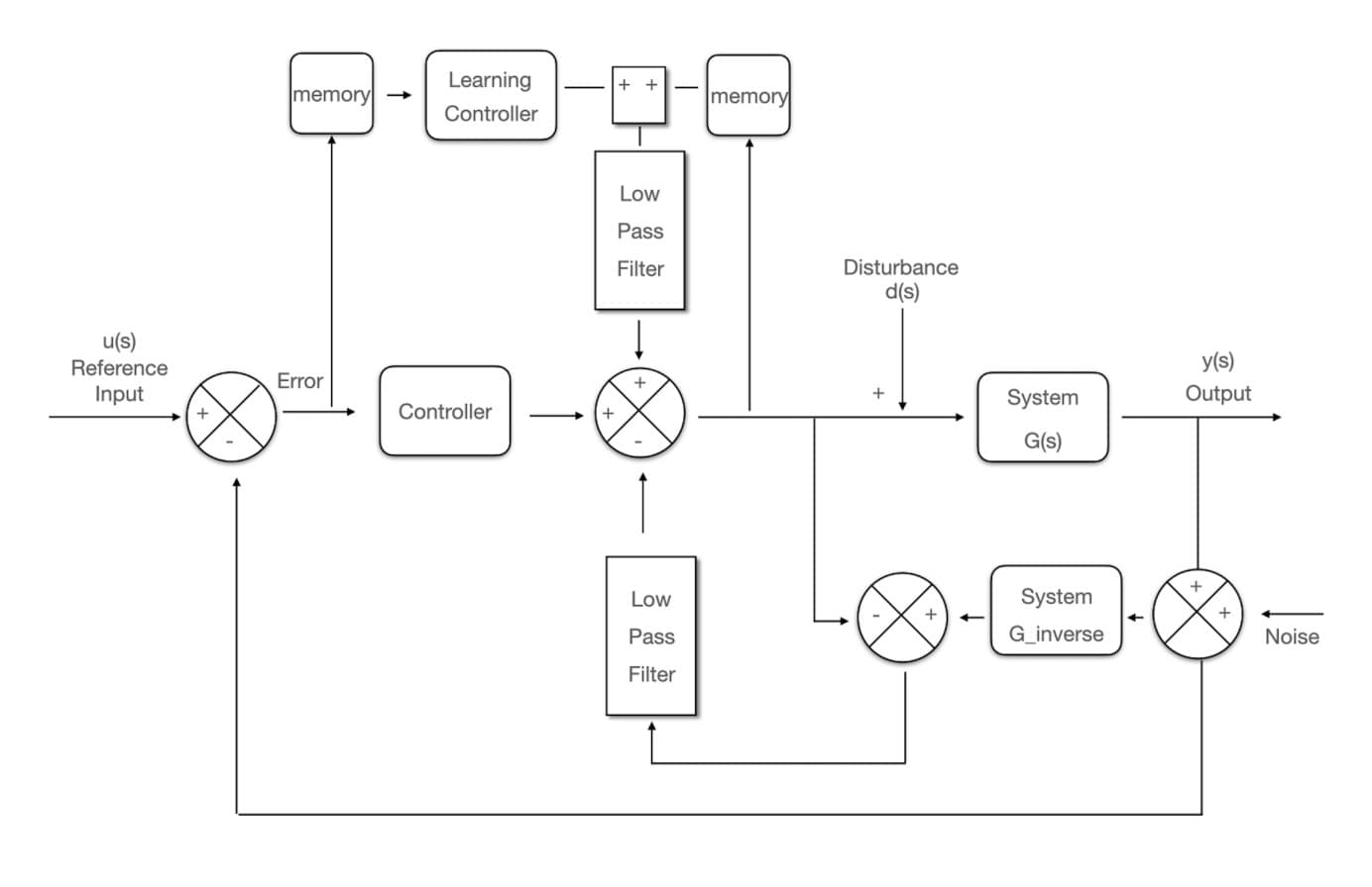
A Disturbance Observer runs the measured output back through the inverse of the nominal plant model and compares the result with the input actually commanded. The difference is an estimate of everything the model didn't account for — friction, backlash, payload shifts, a push on the arm — lumped into a single disturbance term.
Subtracting that estimate from the control input cancels the disturbance in real time. A low-pass filter Q(s) shapes the trade-off: close to 1 where rejection matters, small where sensor noise and model error dominate, and chosen so the observer stays realizable and the closed loop stays stable.
Adaptive Robust Learning is the controller I proposed by integrating the DOB loop inside the ILC framework. The learning term handles the repeatable part of the error across iterations; the observer handles the unrepeatable part within the current one. Two low-pass filters keep the loops from fighting: one smooths what enters the learning memory, the other shapes the disturbance estimate.
The design inverts the usual economics of precision. Instead of machining uncertainty away with CNC parts and imported reducers, ARL treats manufacturing slop as just another disturbance to estimate and cancel — which is exactly what lets a printed PETG arm behave like a far more rigid machine.
ARL control law
uₖ(s) = uₖ₋₁(s) + L·eₖ(s)  // learn across laps
u(s)  = uₖ(s) − d̂(s)       // cancel disturbance
Results
PID vs ILC vs ARL, same arm, same trajectory
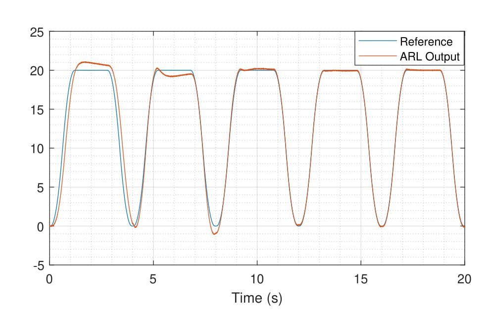
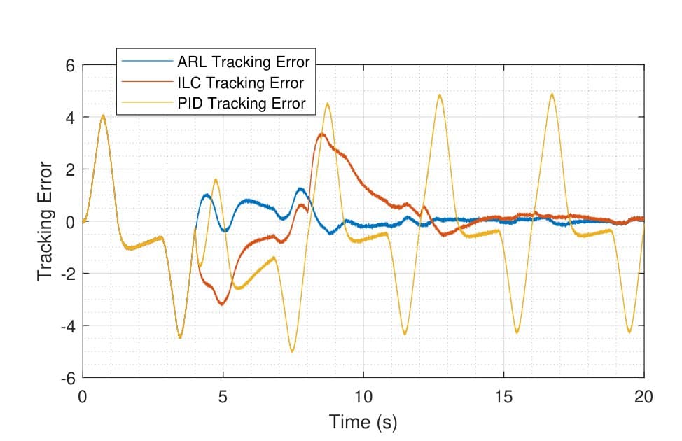
I ran all three controllers on the same reference trajectory with a disturbance injected mid-run. PID repeats its error every cycle and never recovers from the disturbance (RMSE 2.2502). ILC visibly improves lap over lap, but the disturbance around t ≈ 8 s knocks it off and it recovers slowly (1.4697, −34.68%). ARL absorbs the same hit within a cycle and keeps converging (1.004, −55.39%).
The tracking-error comparison tells the story at a glance: the PID trace keeps oscillating forever, the ILC trace decays until it's disturbed, and the ARL trace hugs zero after the first few laps.
Reflection
Integration is the research
Several boards failed during assembly, and I damaged CAN chips twice through incorrect connections. Other failures came from incomplete bills of materials, firmware installation, camera drivers, virtual machines, calibration, and even the orientation-dependent behavior of a dual-purpose USB-C port.
The project taught me that open-source files do not remove engineering difficulty. Every tolerance, electrical connection, dependency, and calibration decision changes the final system. Persistent debugging transformed practical constraints into a publishable control problem.
Next
Toward an intelligent personal robotic assistant
My long-term goal is to extend the platform with language models, speech recognition, richer visual reasoning, responsive kinematics, precise control, and compact high-performance hardware.